
Generate Ramp Layout
To access this screen:
-
Use the
road-testercommand.
Note: This task is part of Interactive Pit Design functionality.
You can design in-pit haulage ramps by creating a set of road rules that you can apply to any pit shell. This gives you a more flexible way to manage ramps over time, such as applying the same rules to a different pit, or to the same pit at a future point in time.
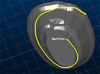
This task supports interactive 3D design, including selecting road milestones, positioning the road to honour target gradients, dynamically updating road position and gradient, and creating multi-road in-pit networks that include switchbacks, for example:
When the command completes, the rules about road construction are written to a road definition table. If the reference road definition table contained data when you started the command, the table may be used to initialise the road layout over the current reference wireframe.
The benefit of this approach is that you can store key design parameters, such as road gradient, target elevations, and switchback configuration, as rules that you can use as an input to the Automated Pit Design task. A key advantage over existing functions such as QUICKPIT is the dynamic, real-time nature of the road editing commands.
Prerequisites and Inputs
The input to this task is a DTM representing an ultimate pit. You can specify this as a loaded surface file, or derive it from an existing OP Reserves project setup by selecting a predefined pit and phase DTM.
For best results, your data should not contain benches. You can still use benched pit surfaces, but you may need additional design work and experimentation to achieve the result you want.
Parameters for Controlling the Layout
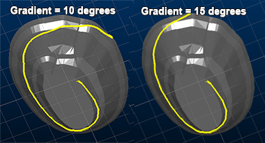
After you define the base surface for generating road strings, you can choose, for each road segment, a target gradient, berm width, and a direction (clockwise or anti-clockwise).
Tip: Ramp design is easier when you use appropriate data snapping options. When you choose a road start position from a pit base, snapping to wireframe data helps. When you conjoin road segments, such as at a switchback to create an in-pit junction, snapping to string data helps. Read More about data selection options....
Task Outputs
Road string data is stored as a 3D file containing explicit geometry. Your design is also saved as a definition file that contains the rules required to apply your design to other pit projects.
Activity steps:
- Display the Generate Ramp Layout screen.
- Select the base surface for road design using Pit/Phase or Surface.
- If you use Pit/Phase, select the required Pit, then select the required Phase and, where available, Value.
- If Pit/Phase is unavailable, associate a planning model with the pit in Define Planning Model, then return to this screen.
- If required, click Reload to redraw the selected surface and load any existing road definition for the selected pit and phase.
- In Scenario, select the scenario that the ramp layout should be associated with.
- In New Road, enter a unique road name, then set the initial road settings such as width, gradient, and direction.
- Use Move Start to place the road start point on the wireframe, and adjust it interactively as required.
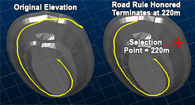
- Use Move End Elevation to set the target end elevation, then review the recalculated road profile.
- Add or remove switchbacks using Add Switchback and Remove Switchback.
- If you need to work from the opposite end of the road, use Reverse Road, then use Move Start to adjust what was previously the termination point.
- Save your design so you have both road string geometry and a definition file containing the rules.
Related topics and activities